
Crimp Sleeve Over Corrugated Tube
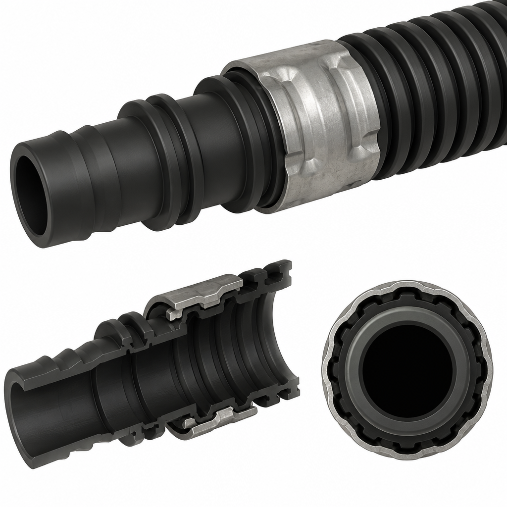
A molded plastic spigot carries two sealing beads and a rear barb profile sized to fit inside the 20 mm corrugated tube bore. The tube end is pushed over t
User Pain Point Description
I want to connect a corrugated tube to an plastic spigot. The tube carries fluid and therefore the connection needs to allow continuous flow, the max pressure is 10 bar. The tube has a diameter of approx. 20mm. There is no axial force during operation. The corrugation is outside which makes it difficult to clamp and seal. The clamping force needs to be large enough to enable a leak free connection. The connection shall be permanent, not reusable. Preferably only hand tools shall be used for assembly.
AI Interpreted Engineering Challenge
Design a permanent connection between a 20 mm corrugated tube and a plastic spigot for continuous fluid flow at high load, using polymer-compatible features, assembled with a tool, and intended for static mechanics. The joint must accommodate external corrugation, provide sufficient clamping force for a leak-free seal at up to 10 bar, and require no reusability or axial load capacity during operation.
AI Generated Concepts
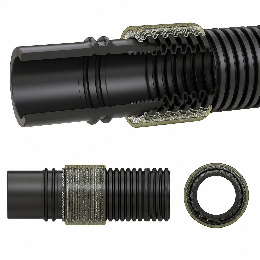
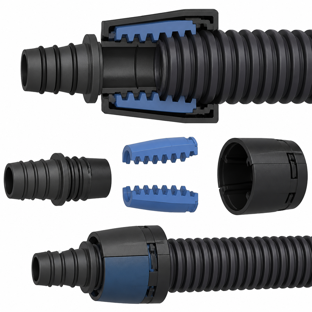
Based on the interpretated engineering challenge, the LLM proposed three different concepts - and this within seconds.
User Selected Concept
The User reviewed the proposed concepts and decided to go forward with the one idea which best solves the technical pain point.
Crimp Sleeve Over Barbed Spigot
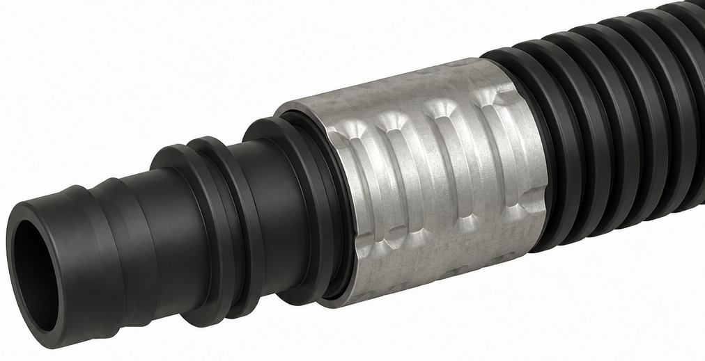
A molded plastic spigot carries two sealing beads and a rear barb profile sized to fit inside the 20 mm corrugated tube bore. The tube end is pushed over the spigot until a hard stop locates it. A separate ductile metal or reinforced polymer crimp sleeve is then placed over the tube OD and compressed with a radial crimp tool. The sleeve has an internal stepped profile so, when crimped, it collapses primarily into selected corrugation valleys, generating high local hoop pressure while avoiding tube buckling. The sealing beads compress the tube liner against the spigot, creating the leak path barrier. Retention comes from mechanical interlock between corrugation valleys, barb faces, and the permanently deformed sleeve.
Pros:
- High clamping force from standard crimp tooling
- Good fit to externally corrugated tube geometry
- Simple load path through sleeve, tube, and spigot
Cons:
- Requires tight crimp process control
- Metal sleeve may affect corrosion specifications
- Permanent assembly cannot be adjusted after crimping
Market potential: high - Familiar crimped hose architecture fits existing assembly lines and addresses many automotive and industrial fluid applications.
Profit-Margin potential: medium - Low part count limits premium pricing, but tooling-compatible reliability supports solid value in volume production.
User Requested Concept Refinement
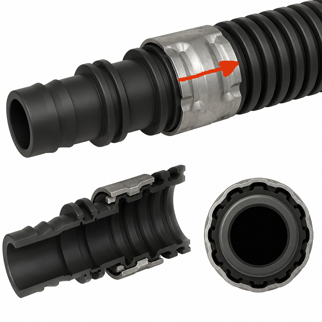
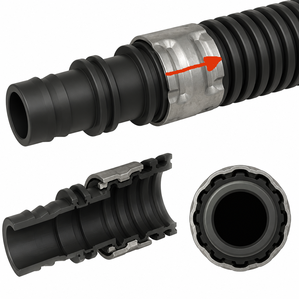
Refinement 1: Increase the crimp sleeve length - direction indicated by red arrow - by 50% in direction of the arrow. Do not change anything else.
Refinement 2: Optimize this idea, make it more suitable for the targeted application, increase robustness, adjust look and feel.
AI Updated Prototype Geometry
A molded plastic spigot carries two sealing beads and a rear barb profile sized to fit inside the 20 mm corrugated tube bore. The tube end is pushed over the spigot until a hard stop locates it. A separate ductile metal or reinforced polymer crimp sleeve, increased in length by 50% in the indicated direction, is then placed over the tube OD and compressed with a radial crimp tool. The sleeve retains its internal stepped profile, collapsing primarily into selected corrugation valleys to generate high local hoop pressure while avoiding tube buckling.
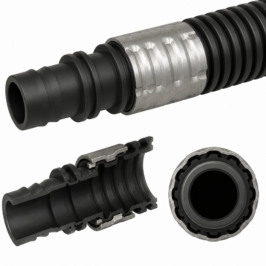
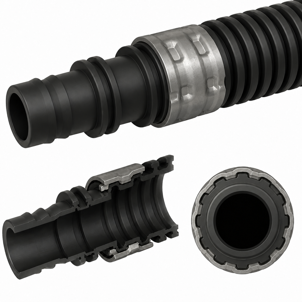
A molded plastic spigot uses dual sealing beads, a positive insertion stop, and a tapered lead-in to protect the tube liner during assembly. The corrugated tube slides over an optimized barb section, then an indexed crimp sleeve with internal valley-forming lands is positioned against a visual stop and radially compressed. The sleeve concentrates force into selected corrugation valleys while leaving relief zones to reduce buckling. A coated metal or glass-filled polymer sleeve option improves corrosion compatibility, and built-in crimp witness features help verify full tool closure and consistent sealing performance.
AI Generated 3D-Printable STL
STL generation 1 used a cropped_image concept image as the source for a prototype mesh.
STL generation 2 used a cropped_image concept image as the source for a prototype mesh.
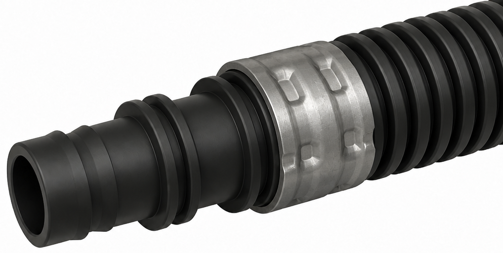
STL generation 3 used a cropped_image concept image as the source for a prototype mesh.
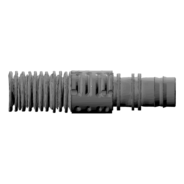
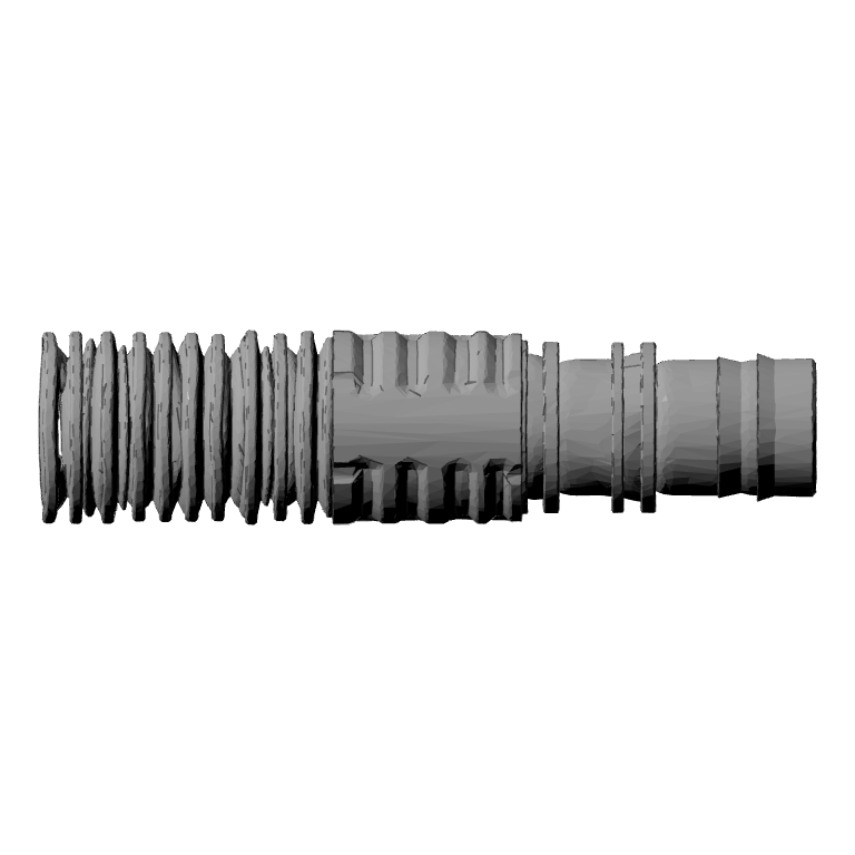
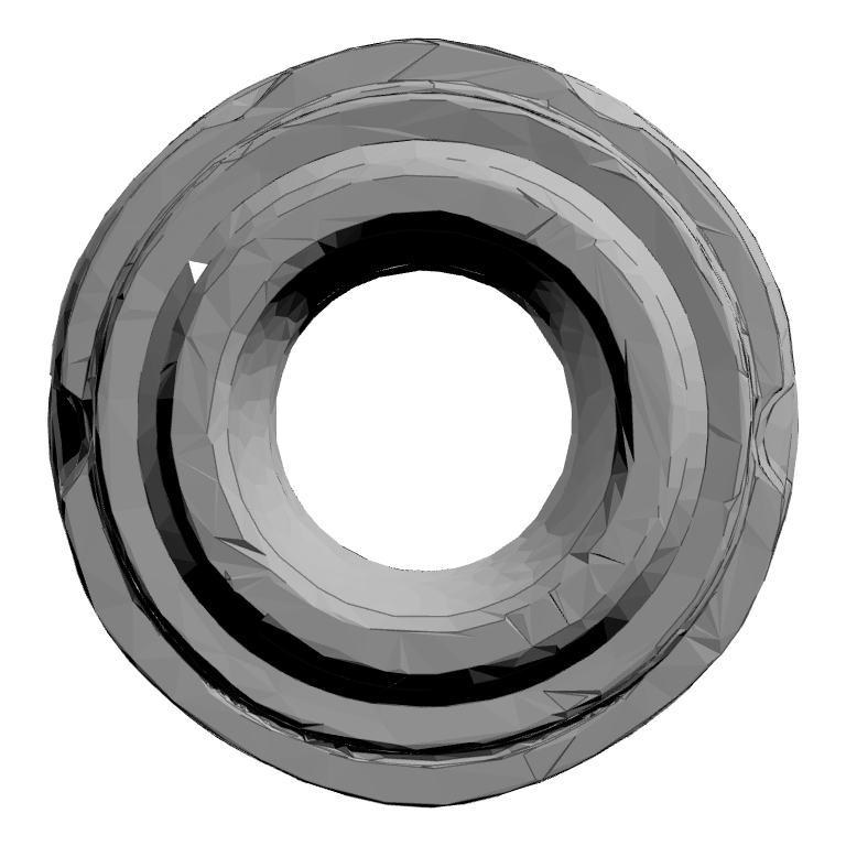
STL generation 4 used a cropped_image concept image as the source for a prototype mesh.
AI Generated OpenSCAD File
The user 3D-printed the STL file and liked the concept. In order to further optimize it and to change specific features, the user let the AIdeator create a parametric OpenSCAD file automatically by AI.
OpenSCAD prototype 1: extended_crimp_sleeve_over_spigot
Approximate bounding box: 1903.44 x 477.04 x 488.54.
Assumptions:
- The long principal axis is X, based on the Front and Top reference views and the strongly elongated bounding box.
- The tube and spigot share a coaxial circular bore centered at Y=0 and Z=0.
- The corrugated tube is represented on the negative-X side, the extended crimp sleeve occupies the central overlap region, and the molded spigot extends toward positive X.
- The sleeve extension requested by the refinement is approximated by a central sleeve length of 600 STL coordinate units.
Validation notes:
- Verify in Front view that the full assembly is centered on Z=0 and that the tube, sleeve, and spigot share the X axis.
- Verify in Top view that the bore remains circular and concentric with all external rings.
- Verify in Right view that the maximum radial envelope remains within the approximately 477 by 489 source envelope.
- Check the sleeve-to-tube overlap at the named sleeve_start_plane_x and sleeve_end_plane_x guard planes.
Engineering Assessment by the User
EDIT BEFORE PUBLISHING: add the manual engineering assessment, validation status, limitations, and conclusion.
Try AIdeator with your own engineering problem
Start from a technical pain point and build a concept package for manual review.
Try AIdeator Now Back to AIdeator home