
Spring Band Earbud Retainers
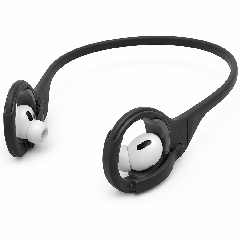
A thin, flexible polymer band spans behind the head and terminates in two side-mounted earbud retainers positioned behind each ear. Each retainer includes
User Pain Point Description
The diagram shows a pair of earphones – these are two separate earpieces: the left and the right. I want to design a holder that: 1. will hold both earpieces together, 2. allows me to run whilst wearing them; 3. ensures there is no risk of one or both falling out of my ears whilst running; 4. ensures there is no risk of one or both detaching from the holder whilst running; 5. allows for easy attachment and removal of the earphones from the holder; 6. the holder can be made in different colors, 7. the holder will not rub against the area around the ear – ideally, contact with the ear should be minimal, and if contact is necessary, the holder should be made of a material that does not cause chafing. 8. inserting and removing the earphones from the holder will not scratch their surface
AI Interpreted Engineering Challenge
Design a low-load polymer holder for two separate earphone earpieces used during dynamic running conditions. The holder must manually attach and remove the earpieces securely, preventing earbud loss from the ears or detachment from the holder. Minimize contact and chafing around the ear, protect earphone surfaces from scratches during insertion, and support production in multiple colors.
AI Generated Concepts
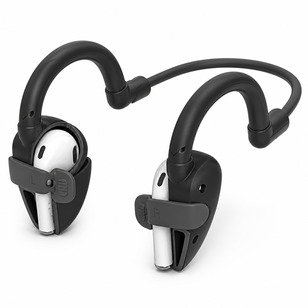
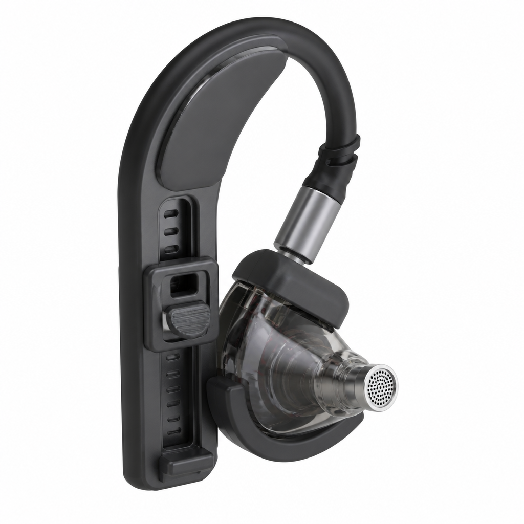
Based on the interpretated engineering challenge, the LLM proposed three different concepts - and this within seconds.
User Selected Concept
The User reviewed the proposed concepts and decided to go forward with the one idea which best solves the technical pain point.
Spring Band Earbud Retainers
A thin, flexible polymer band spans behind the head and terminates in two side-mounted earbud retainers positioned behind each ear. Each retainer includes a shallow C-shaped shell that sits outside the ear and a pivoting latch arm connected by a molded living hinge at the lower rear corner. The earphone is inserted from the side into a padded pocket, with its main body nested inside the C-shell and its in-ear nozzle passing through an open front clearance toward the ear canal. The latch arm rotates around the living hinge and snaps into a small receiving notch on the opposite side of the shell, forming a closed loop around the earphone body. Internal silicone-like TPU contact pads touch only smooth exterior surfaces. The band load path runs from one earbud shell through the rear band to the opposite shell. The latch must clear the earphone during opening and must not cross microphone or speaker openings when closed.
Pros:
- Simple single-piece band with two latch modules
- Strong resistance to accidental earbud detachment
- Easy manual opening with rear-facing tabs
Cons:
- Living hinge durability requires material validation
- May interfere with glasses arms
- Band tension must fit multiple head sizes
Market potential: high - A universal sports accessory can appeal to runners, gym users, and commuters.
Profit-Margin potential: high - Low part count and injection-molded construction support economical high-volume manufacturing.
User Requested Concept Refinement
Refinement 1: Optimize this idea, make it more suitable for earphone, which I have shown on attached picture and are used in concept: Dual Earhook Snap Cradles
Refinement 2: Optimize this idea, make it more suitable for earphone, which I have shown on attached picture and are used in concept: Dual Earhook Snap Cradles means that on generated picture I can see "in-ear headphones" but should be regular earphones.
Refinement 3: attaché both earphones in holes shown by red arrows.
Refinement 4: move both earphones in direction shown by red arrows till speaker part will be in touch with holder
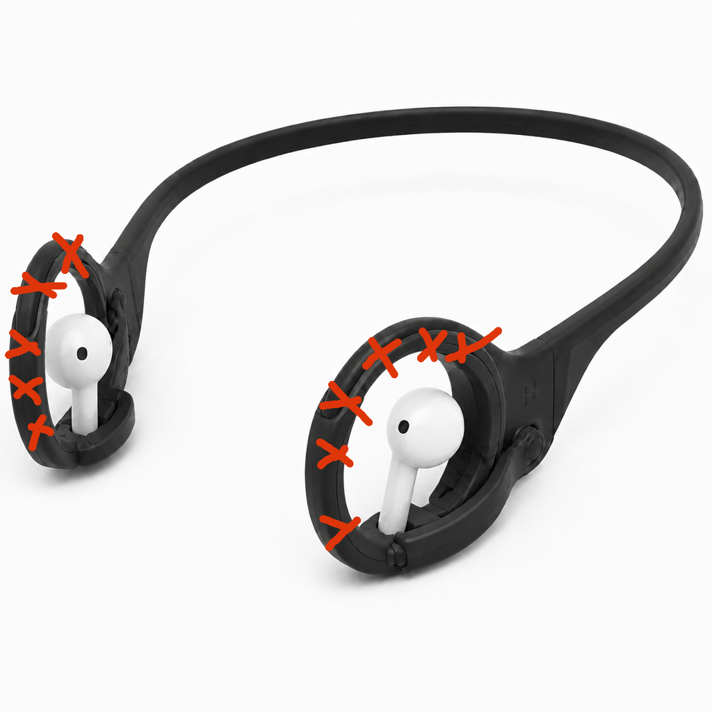
Refinement 5: remove symetrically from both sides part of holder which is marked by red crosses
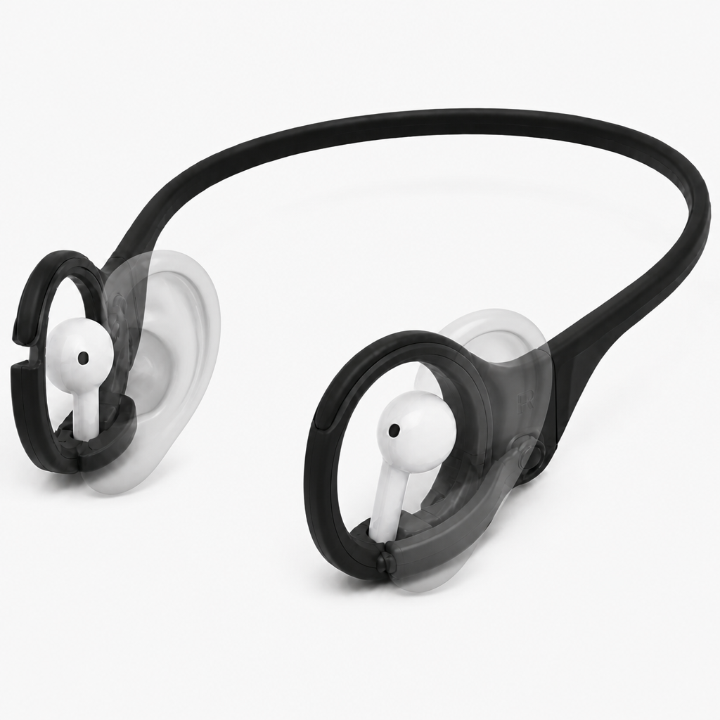
Refinement 6: add shape of ears as semitransparent to visualize how they will look on head.
AI Updated Prototype Geometry
A thin, flexible polymer band spans behind the head and ends in two low-profile retainers positioned behind each ear. Each retainer combines a shallow C-shaped outer shell with a soft TPU-lined pocket centered above and behind the earlobe. The earphone slides sideways through a flared entry clearance until its body rests against three TPU contact pads. A separate flexible latch arm pivots on a small rear pin hinge rather than a living hinge, then snaps into a front receiving notch to close around a smooth non-button portion of the housing. The open front clearance leaves the nozzle unobstructed toward the ear canal, while recessed pad zones avoid microphones, speaker ports, charging contacts, and touch surfaces. A short sliding section in the rear band allows fit adjustment without increasing earhook pressure.
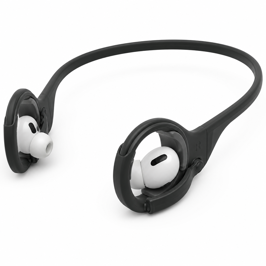
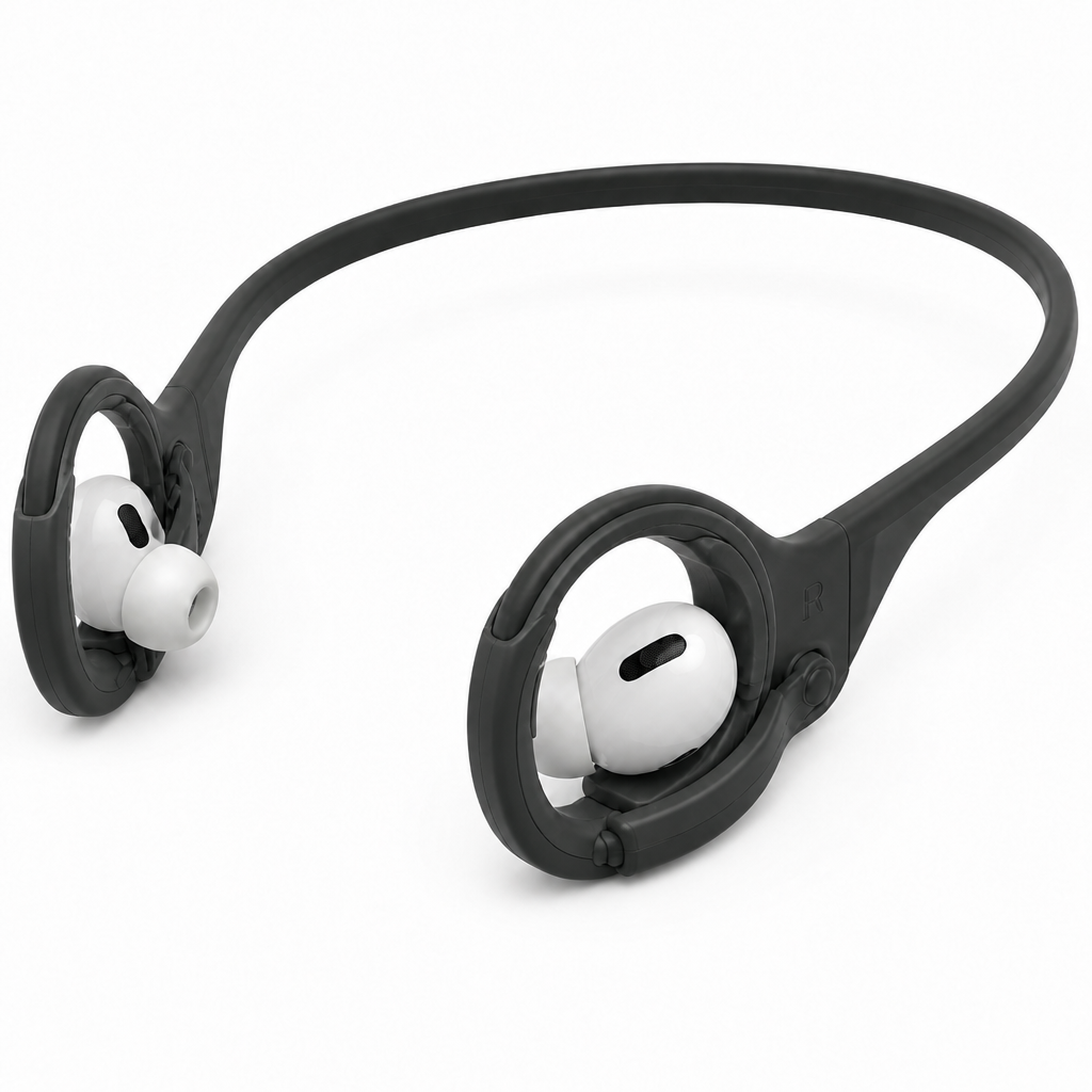
A thin flexible polymer band spans behind the head and terminates in two compact retainers seated behind each ear. Each retainer is reshaped for regular stemmed wireless earphones: a shallow C-shaped shell wraps around the rounded main housing above and behind the earlobe, while an open lower channel lets the stem hang freely without contact. The earphone enters sideways through a flared slot and settles against three soft TPU contact pads on the housing’s smooth outer surface. A rear pin-hinged latch swings over the housing and snaps into a front notch, leaving clear space around speaker grilles, microphones, touch zones, charging contacts, and the ear-facing nozzle.
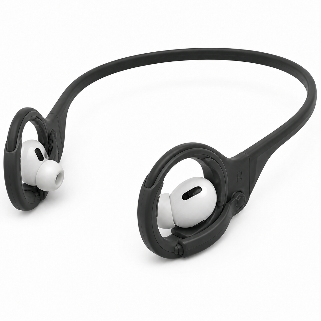
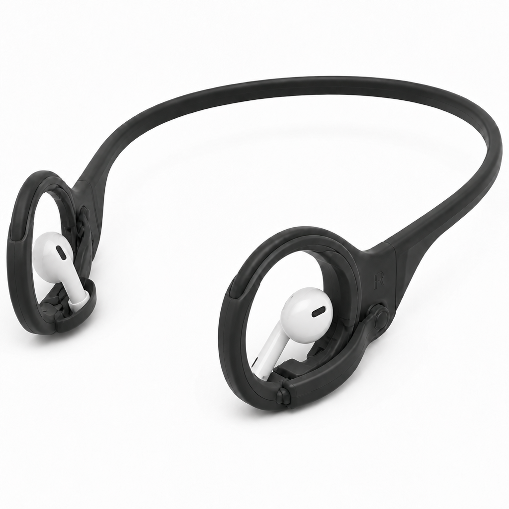
A thin flexible polymer band spans behind the head and ends in compact retainers positioned behind each ear. Each retainer includes a rounded receiving hole sized to accept the main housing of a regular stemmed earphone from the outer side. The housing sits inside the hole against three soft TPU contact pads, while a lower open slot allows the stem to hang downward without contact. A small rear pin-hinged latch closes across the hole opening and snaps into a front notch, preventing the earphone from backing out. The ear-facing nozzle, speaker grilles, microphones, touch surfaces, and charging contacts remain outside the cradle contact areas.
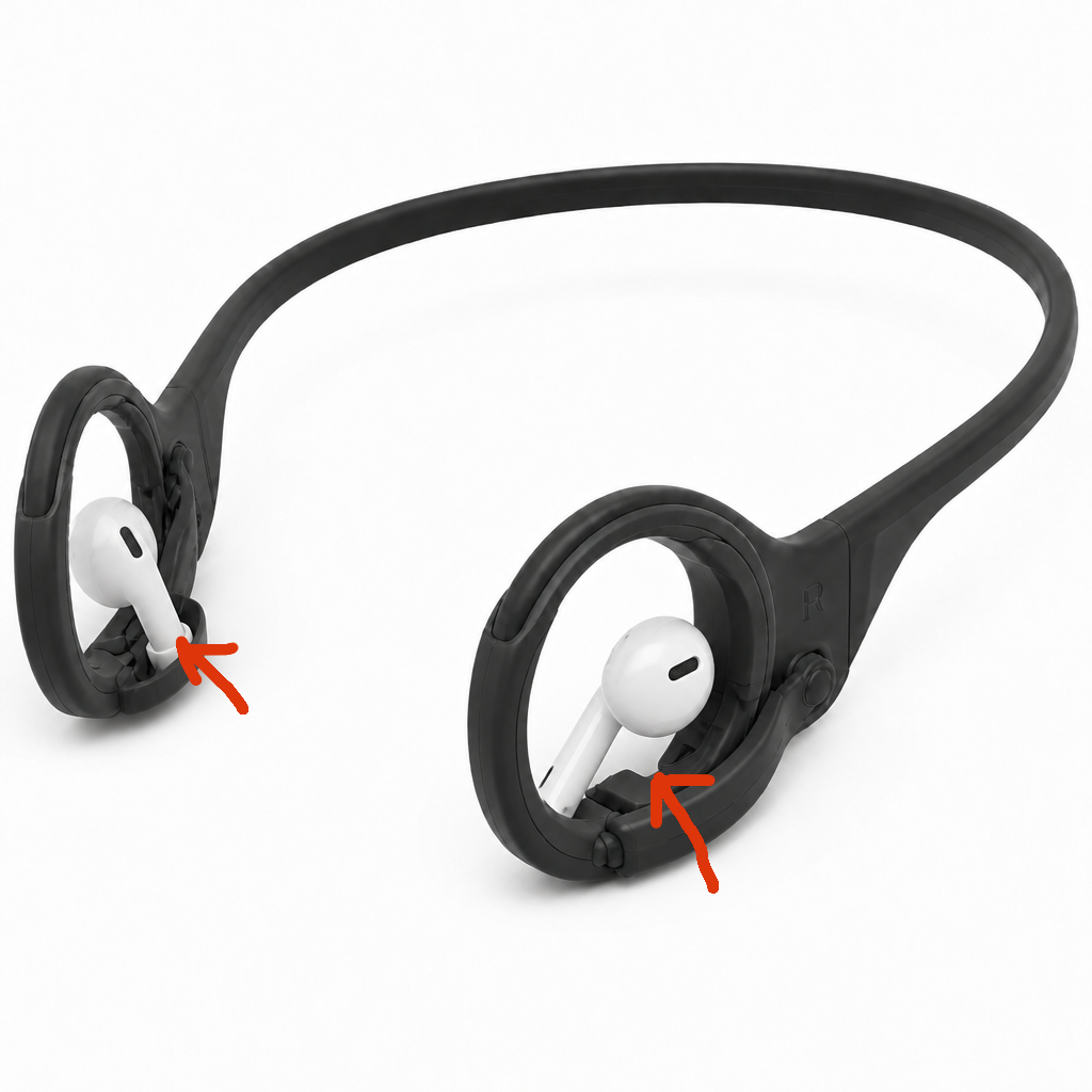
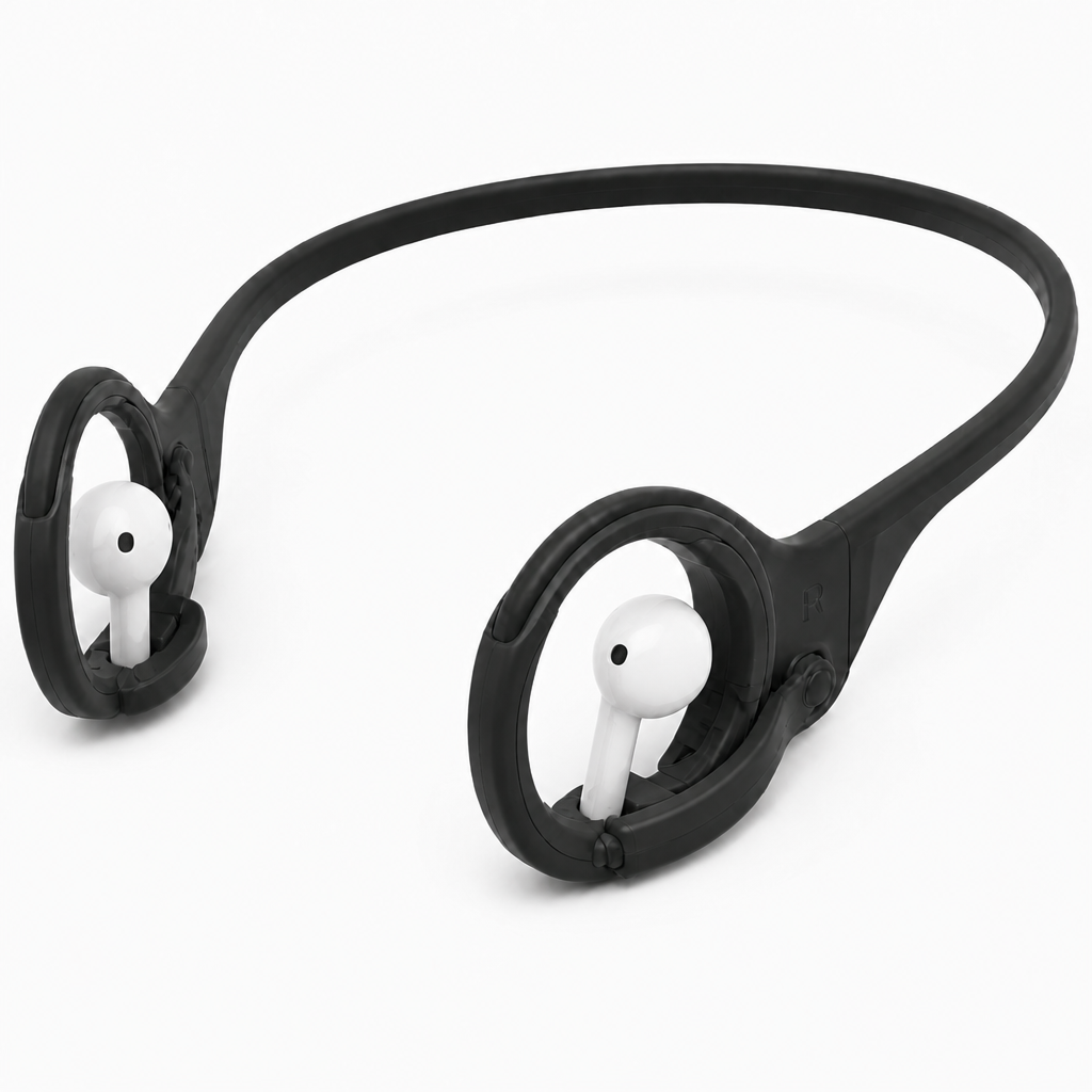
A thin flexible polymer band spans behind the head and ends in compact retainers behind each ear. Both stemmed earphones are moved fully inward from the outer side of their respective rounded receiving holes until each speaker housing reaches the holder. Each earphone’s speaker-side outer rim rests against a soft TPU annular contact seat inside the cradle, while a small central clearance prevents blockage of the speaker grille or nozzle. Three surrounding TPU pads stabilize the housing without touching microphones, touch surfaces, or charging contacts. A lower open slot lets each stem hang downward freely. A rear pin-hinged latch closes across each hole and snaps into a front notch.
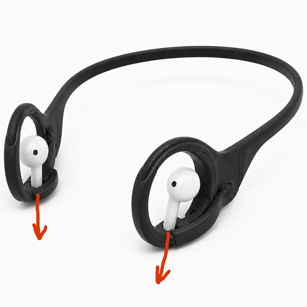
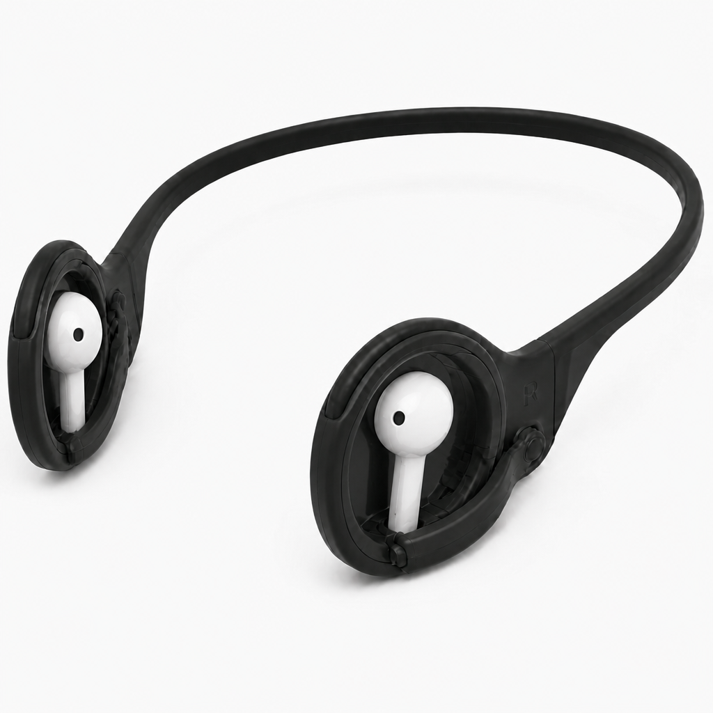
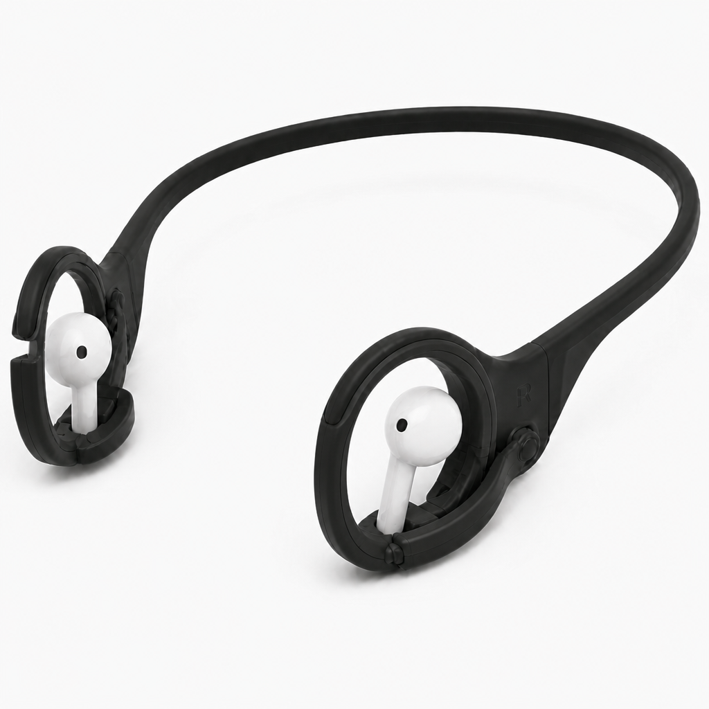
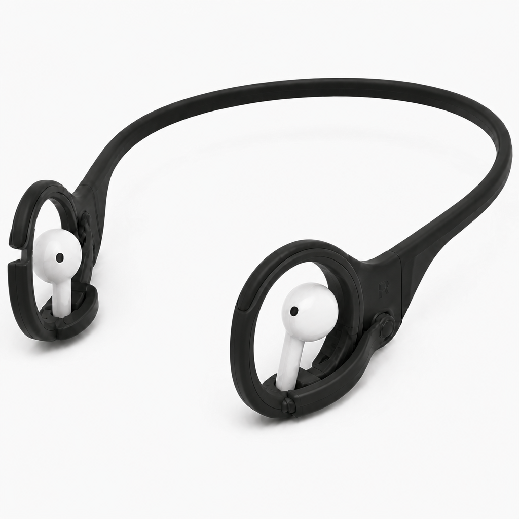
A thin flexible polymer band spans behind the head and ends in compact retainers behind each ear. Both retainers are symmetrically trimmed on their outer side walls, removing the marked excess material while preserving a rounded receiving bore for each earphone housing. Each housing enters from the outer side and rests against three soft TPU contact pads inside the bore. A lower open slot lets the stem hang downward with clearance. A small rear pin-hinged latch closes across the bore opening and snaps into a front notch. The ear-facing nozzle, speaker grilles, microphones, touch surfaces, and charging contacts remain clear of all cradle surfaces.
A thin flexible polymer band spans behind the head and ends in compact retainers positioned behind semitransparent ear forms, making the over-ear fit and clearance visible. Both retainers remain symmetrically trimmed along their outer side walls while preserving rounded receiving bores for the earphone housings. Each housing enters from the outer side and rests on three soft TPU contact pads inside its bore. A lower open slot allows the stem to hang downward without touching the cradle. A rear pin-hinged latch closes across each bore opening and snaps into a front notch. The semitransparent ears show that no cradle surfaces obstruct the ear canal, nozzle, speaker grilles, microphones, touch surfaces, or charging contacts.
AI Generated 3D-Printable STL
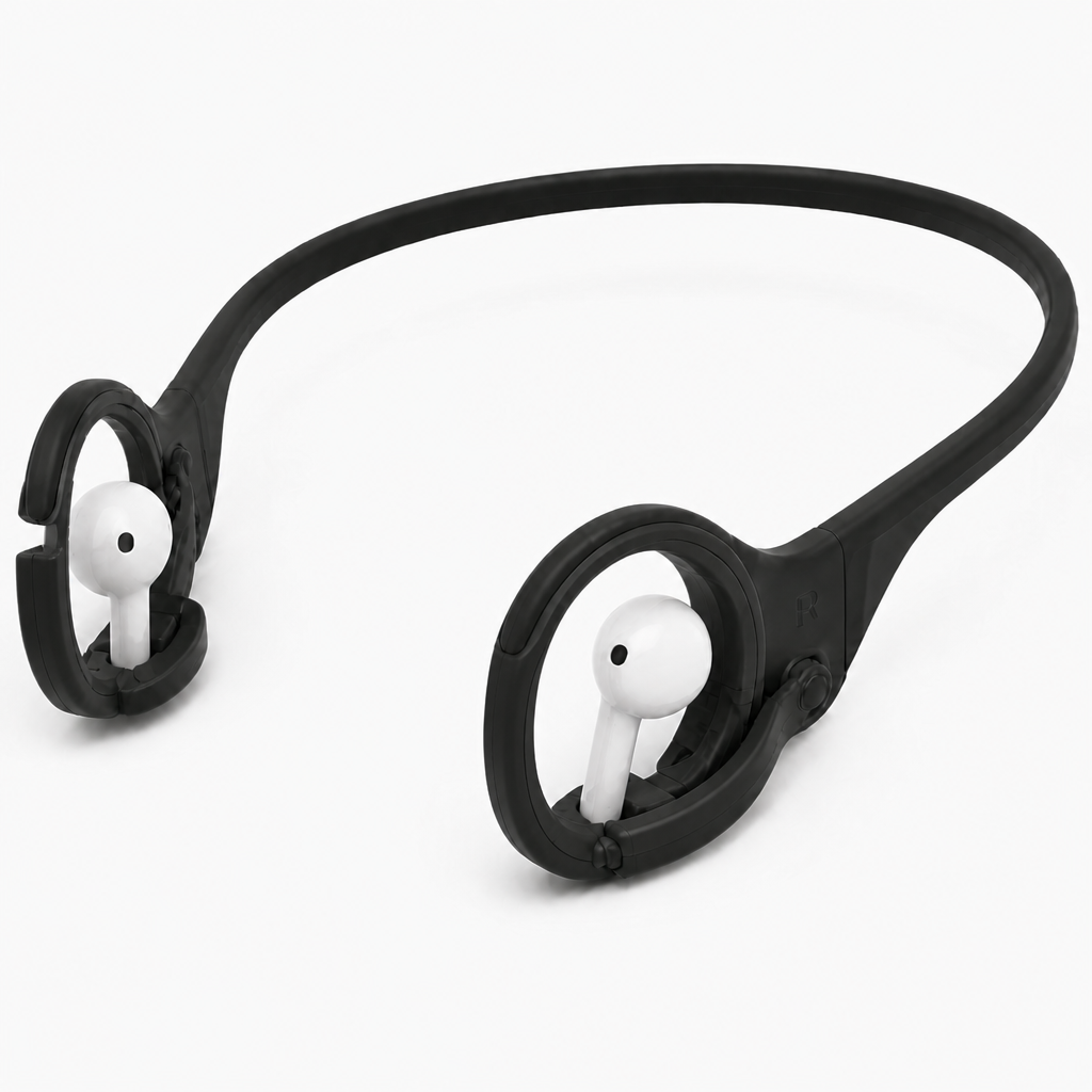
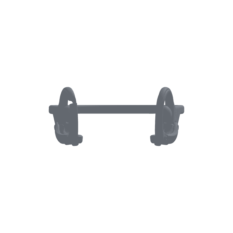
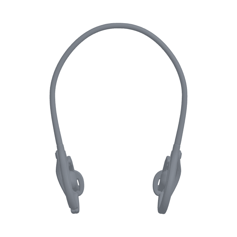
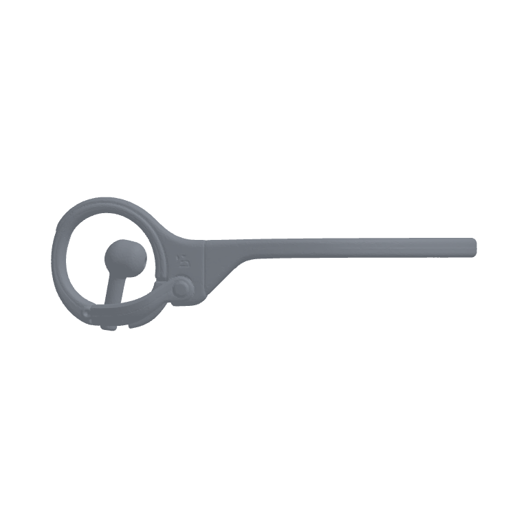
STL generation 1 used a full_image concept image as the source for a prototype mesh.
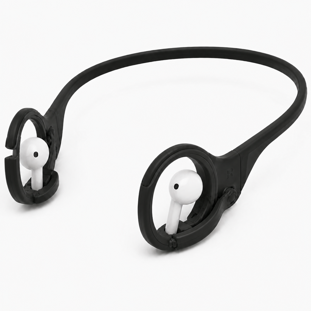
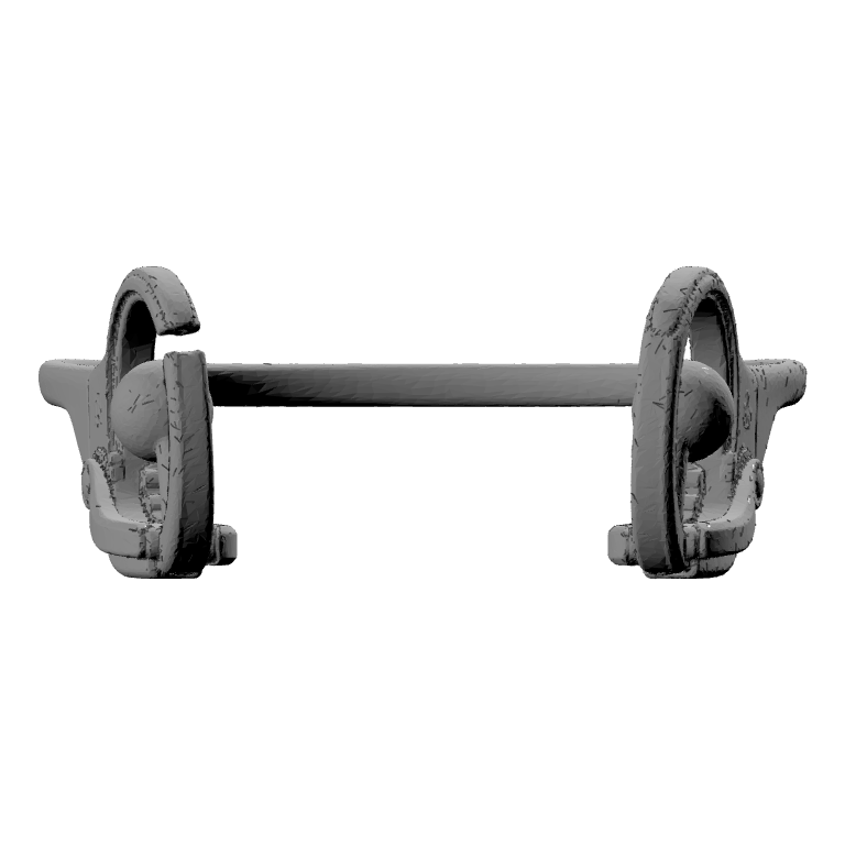
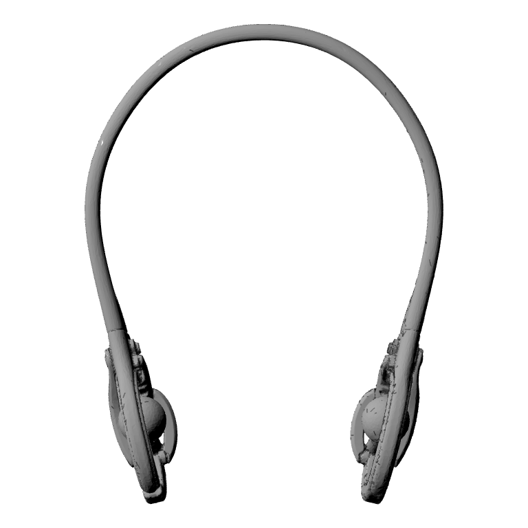
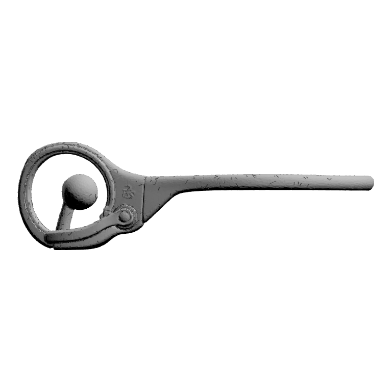
STL generation 2 used a full_image concept image as the source for a prototype mesh.
AI Generated OpenSCAD File
The user 3D-printed the STL file and liked the concept. In order to further optimize it and to change specific features, the user let the AIdeator create a parametric OpenSCAD file automatically by AI.

OpenSCAD prototype 1: symmetrical_earphone_lock_cradles
Approximate bounding box: 1368.70 x 1899.05 x 597.04.
Assumptions:
- The STL coordinate system is interpreted with X as left-right width, Y as front-rear headband depth, and Z as vertical height.
- The top-view silhouette is treated as the primary datum for the U-shaped rear head band.
- Each earphone housing bore is modeled with its axis along X, producing a circular receiving opening in the Y-Z cradle plane.
- The model is a deliberately simplified reconstruction; organic contours, fillets, living-hinge details, snap teeth, logos, grilles, microphones, and exact TPU pad geometry are omitted.
Validation notes:
- All primary geometry is positioned from shared band endpoint and cradle-center datums.
- Left and right retainers use the same cradle module and are mirrored by a signed side datum.
- The head band terminates at the upper-rear attachment region of each cradle rather than using unrelated placement translations.
- The receiving bore is fully cut through each cradle along the X axis.
OpenSCAD prototype 2: symmetrical_earphone_lock_cradles_simplified
Approximate bounding box: 1368.70 x 1899.05 x 597.04.
Assumptions:
- The model coordinate system follows the supplied brief: X is left-to-right width, Y is front-to-back depth, and Z is height.
- The assembly is symmetric about the YZ plane at X=0.
- The large visible earphone receiving openings are approximated as circular bores whose axes run along Y.
- The main band is modeled as a smooth round flexible polymer member using hulled spheres rather than a mesh-derived swept profile.
Validation notes:
- All major locations are derived from shared assembly centerline and cradle-center datums.
- The mirrored cradle module receives only side direction as an input, avoiding unrelated per-side placement guesses.
- The band endpoints overlap the attachment neck volumes intentionally to form a continuous structural load path.
- Receiving bores remain open through the full cradle depth along Y.
OpenSCAD prototype 3: symmetrically_trimmed_earphone_lock_cradles_refined
Approximate bounding box: 1368.70 x 1899.05 x 597.04.
Assumptions:
- STL coordinate units are retained without applying a physical-unit scale.
- The dominant headband path is modeled in the shared XY datum plane, with X defining left-right width, Y defining front-rear depth, and Z defining thickness/vertical extent.
- Earphone receiving bores are modeled with their axes along X so the main cradle profile is visible in the YZ side view.
- The exact organic shell contours, living-hinge detail, latch snap geometry, fine texture, logos, small ribs, and detailed earbud geometry are intentionally omitted.
Validation notes:
- All major bodies are positioned from shared center, band endpoint, and cradle center datums.
- Left and right cradle modules are generated from the same side parameter and remain symmetric about X = 0.
- The receiving bores are open through the cradle depth and include lower stem clearance slots.
- Contact pads are separate simplified soft-interface bodies positioned inside each bore.
OpenSCAD prototype 4: symmetrical_earphone_lock_cradles_simplified
Approximate bounding box: 1368.70 x 1899.05 x 597.04.
Assumptions:
- The supplied STL coordinate system is used directly, with X as left-right width, Y as front-back depth, and Z as height.
- The rear band is represented as a circular-section swept path in the X-Y plane, with a constant elevated Z datum.
- Each earphone housing enters through a bore whose axis is aligned with X, consistent with a left/right side-entry cradle arrangement.
- The original textured and organically filleted STL surfaces are approximated using cylindrical annuli, spheres, hulls, and simple rectangular cuts.
Validation notes:
- The model is symmetric about the Y-Z plane at X=0.
- Both receiving bores are true through-bores along X and remain clear of the outer shell material.
- The lower slot cuts through the lower-forward portion of each cradle, creating a visible stem-clearance opening.
- The rear band is located from shared end attachment datums and arch control points rather than arbitrary independent placement.
OpenSCAD prototype 5: symmetrical_trimmed_earphone_lock_cradles
Approximate bounding box: 1368.70 x 1899.05 x 597.04.
Assumptions:
- STL coordinate units are retained directly without assigning millimetres or applying a final sizing scale.
- The X axis is the left-right width datum, Y is the front-back/depth datum, and Z is the vertical datum.
- The rear headband lies predominantly in the X-Y plane and reaches its rear-most extent at positive Y.
- Each earphone body is represented by a bore whose axis is parallel to X, matching the circular cradle profile visible in the right orthographic view.
Validation notes:
- The model is symmetric about the Y-Z plane and all left/right component locations derive from the shared cradle centerline datum.
- The headband endpoints, cradle transitions, latches and pads reference shared cradle and band datums rather than unrelated world translations.
- Central earphone bores are open through the full shell width.
- A lower stem-clearance slot is cut continuously from each bore to the lower exterior.
OpenSCAD prototype 6: Symmetrically Trimmed Earphone Lock Cradles
Approximate bounding box: 1368.70 x 1899.05 x 597.04.
Assumptions:
- Dimensions retain the approximate proportional intent of the rejected STL-derived reconstruction.
- X is the left-to-right width axis, Y is the front-to-back depth axis, and Z is vertical.
- Earphone body bores are open along Y so inserted earphones would face toward the front and rear.
- The outer carrier walls are intentionally trimmed on the outside of each cradle.
Validation notes:
- The code defines the required assembly_base() module and contains no final module invocation.
- All reconstructed visible geometry is contained within assembly_base().
- The left and right cradles are generated from a shared loop and mirrored using the side sign.
- Receiving bores and lower stem slots are subtracted from each carrier plate.
OpenSCAD prototype 7: Symmetrically_Trimmed_Earphone_Lock_Cradles
Approximate bounding box: 1368.70 x 1899.05 x 597.04.
Assumptions:
- X is left-right, Y is front-back, and Z is vertical.
- The rear head band is positioned at negative Y and spans between the two cradle locations.
- Earphone housings are omitted so the retaining bores, contact pads, latch mechanisms, and stem openings remain visible.
- Each cradle uses a toroidal retaining ring with a lower rectangular stem-clearance opening.
Validation notes:
- The required top-level module assembly_base() is defined and contains the complete reconstructed assembly geometry.
- No final module invocation is present.
- No import, include, use statement, file reference, sizing wrapper, or scaling wrapper is present.
- Both cradle assemblies are generated from a shared ear-center datum using side_sign values of -1 and 1.
OpenSCAD prototype 8: symmetrically_trimmed_earphone_lock_cradles
Approximate bounding box: 1418.79 x 1899.39 x 577.21.
Assumptions:
- The supplied orthographic images indicate a symmetric behind-the-head wearable with X as left-right width, Y as front-rear depth, and Z as vertical height.
- The large circular retainer openings are modeled with bore axes parallel to X, consistent with the side-view circular shell silhouette.
- The STL bounding box is used only as the shared overall coordinate envelope; all dimensions remain editable STL coordinate units.
- The exact triangulated outer contours, surface texture, micro-ribs, logos, charging details, microphone openings, and living-hinge internals are intentionally omitted.
Validation notes:
- Both retainers are located from the shared X symmetry plane using plus/minus holder_axis_x; no independently guessed left/right placement is used.
- The rear band is constructed from linked stations whose end coordinates are derived from each retainer's rear tangent datum.
- Each latch pin, latch arm, front snap lug, bore, housing, nozzle, stem slot, and contact pad is located from the common holder center, bore axis, hinge datum, or snap datum.
- The nozzle follows the X-axis receiving-bore centerline toward the global center plane.
OpenSCAD prototype 9: symmetric_earphone_lock_cradles
Approximate bounding box: 1418.79 x 1899.39 x 577.21.
Assumptions:
- The large U-shaped structure visible in the Top view is interpreted as the rear flexible head band, lying predominantly in the XY plane at approximately Z = 0.
- The circular retainer bores are interpreted as coaxial with the global X axis because the Right YZ view shows the receiving loop face-on.
- The rounded spherical forms visible within each retainer are represented as simplified retained earphone housings rather than attempting to reconstruct detailed earbud meshes.
- The lower-front gap in each annular shell is treated as the stem clearance slot, while the lower rear hinge and sweeping lower latch close that opening.
Validation notes:
- Check Front XZ view: the rear band should span between symmetric left and right retainers at approximately the global mid-height.
- Check Top XY view: the band should form a broad rearward U-shape, with both cradle assemblies placed symmetrically near the front depth side.
- Check Right YZ view: the cradle bore should read as a circular loop with its axis normal to the view, and the band should exit rearward toward positive Y.
- Adjust cradle_center_y, band_end_depth, and band_rear_depth together if the source view indicates a different front-to-rear head-band curvature.
Engineering Assessment by the User
EDIT BEFORE PUBLISHING: add the manual engineering assessment, validation status, limitations, and conclusion.
Try AIdeator with your own engineering problem
Start from a technical pain point and build a concept package for manual review.
Try AIdeator Now Back to AIdeator home